

With the proliferation of high-speed peripherals in systems design, interface compliance has become a non-negotiable requirement. In particular, the USB 3.0 (SuperSpeed USB) standard demands stringent verification of physical-layer parameters, signal integrity and jitter performance. The RIGOL DS80000 Series oscilloscope, paired with the dedicated USB 3.0 Compliance Test software option, offers a powerful platform for performing full physical-layer compliance testing of USB3 links.
Why Use the DS80000 Series for USB 3.0 Compliance
High-performance acquisition
The DS80000 family supports analogue bandwidths up to 13 GHz and real-time sampling up to 40 GSa/s on each channel. Deep memory depth (up to 4 Gpts) enables long capture windows with high resolution.
These specifications ensure the instrument can capture the fast edge transitions and high-frequency spectral content of USB 3 links, which operate at up to 5 Gb/s for the original SuperSpeed USB standard.
Built-in compliance-oriented software
RIGOL provides a dedicated USB 3.0 Compliance Test software option (model DS80000-USB3C) which integrates measurement routines, analysis templates and reporting – enabling engineers to focus on the test rather than building their own measurement scripts.
Multi-protocol capability
Beyond USB 3.0, the DS80000 series supports a broader range of physical-layer compliance tests (e.g., USB 2.0, MIPI D-PHY, Ethernet) which means the test platform can be reused for multiple interface validation tasks.
Test Setup: Hardware and Software
Hardware components
Oscilloscope – A DS80000 series model (e.g., DS81304) with sufficient bandwidth (≥ 6 GHz recommended, ideally 10–13 GHz) and the USB 3.0 compliance software option.
Probes / front-end – Use appropriate high-speed differential probes or active probes compatible with SuperSpeed USB signal levels and with the RIGOL SmartProbe 2.0 interface if supported.
Device Under Test (DUT) – A USB3 host or device interface requiring compliance verification.
Test fixture / adapter – A high-bandwidth, low-distortion connection to tap into the SuperSpeed USB signal (for example, differential pair of TX/RX lanes). With USB3, maintain proper impedance (typically 90 Ω differential) and minimise signal distortion.
Setup checklist
- Confirm the bandwidth of your scope model is adequate for USB3-5Gb/s testing (≥ 6 GHz, preferably higher).
- Connect the differential probe across the USB lane you wish to test (Tx or Rx). Maintain a proper ground/return reference or a matched pair termination network.
- Set the oscilloscope input channel to 50 Ω (or 1 MΩ if appropriate) and adjust coupling (DC or AC) as required. For high-speed differential signals, 50 Ω single-ended or differential mode is typical.
- Verify signal integrity (e.g., correct amplitude, no gross distortion) before launching the compliance test software.
Procedure: Performing a USB 3.0 Compliance Test
Below is a typical step-by-step flow using the DS80000 and the USB 3.0 compliance software.
- 1. Initial signal capture
o Trigger the DUT into a link state that transmits USB data.
o Capture a short waveform to verify the signal looks reasonable: correct amplitude (~400–800 mV differential for SuperSpeed USB), clean transitions, no obvious ringing or overshoot.
o If the waveform is poor, review your probe connection, grounding and fixture design. - 2. Load compliance template
o From the software menu, select the USB 3.0 compliance test template. The software will configure the oscilloscope with the correct acquisition settings (e.g., sample rate, memory depth, pre- and post-trigger) and measurement routines. - 3. Run Eye Diagram capture
o The tool captures multiple bits of data and constructs an eye-diagram view. Typical measurements include eye height, eye width, crossing, jitter (total jitter, RJ/DJ), amplitude, and rise/fall times.
o Ensure the capture window length and number of waveforms is adequate per the standard’s requirement. - 4. Jitter and amplitude analysis
o The software automatically computes jitter metrics (total jitter at specified bit error rate, random jitter, deterministic jitter) and amplitude margin.
o Compare these values against the USB 3.0 specification limits. - 5. Spectral and channel margin checks
o Some compliance checks include verifying spectral content (to ensure no excessive harmonic content or EMI issues) and channel loss margins. The software may optionally support these analyses.
o Insert any necessary cable/fixture losses or attenuations into the measurement arithmetic to account for test-setup impact. - 6. Automated pass/fail decision and report generation
o Once all measurement metrics are obtained, the software auto-compares them to the defined thresholds and provides a pass/fail decision.
o Generate a PDF report (or other format) documenting the test conditions, measurement results, screenshot of eye diagram(s), and pass/fail status. - 7. Repeat for all required lanes and conditions
- 8. USB 3.0 comprises differential transmit and receive lanes; you should test each lane in both directions as applicable.
- 9. Also test under multiple operating conditions (e.g., different cable lengths, host/device states, temperature extremes) if required by your product compliance plan.
Key Measurements and Interpretation
Below are some of the crucial measurements you will monitor during the USB 3.0 compliance test, along with guidance on how to interpret them.
| Parameter | Description |
| Eye height (vertical opening) | Measures the vertical voltage margin of the eye diagram. A larger eye height gives more tolerance to noise and amplitude variation. |
| Eye width (horizontal opening) | Indicates the timing margin: the wider the eye, the more tolerance to jitter and skew. |
| Total jitter (TJ) | Total timing deviation measured at a given bit error rate (e.g., BER = 10⁻¹²). |
| Random jitter (RJ) & Deterministic jitter (DJ) | Breakdown of total jitter: RJ is statistical, DJ is predictable pattern timing jitter. Helps isolate sources of jitter (e.g., power supply noise, crosstalk). |
| Rise/fall times | The transition speed of differential signals (e.g., 20–80% amplitude). Faster edges are good, but too fast may introduce overshoot/reflections. |
| Amplitude swing & overshoot/undershoot | The differential peak-to-peak voltage, and any overshoot or undershoot beyond the nominal amplitude. Excessive overshoot can degrade eye opening and increase EMI risk. |
| Spectral content / harmonic distortion | Some compliance tests require checking that harmonics and emissions are within defined limits. |
When reviewing results, ensure that each lane (Tx/Rx) of your DUT meets the requirements and that test setup losses or probe/fixture degradations have been accounted for. For example, if your fixture adds 1 dB of attenuation, include that in the measurement margin.
Practical Tips to Accelerate Testing
- Probe & fixture design matter: For SuperSpeed USB, even small mismatches or reflections degrade the eye. Use high-bandwidth differential probes, keep wiring as short as possible, and match impedance correctly (≈ 90 Ω differential).
- Ensure calibration and signal integrity: Run a pre-test check of your setup (probe compensation, verification of amplitude, rise/fall times) before the formal compliance test.
- Use the automated software features: The RIGOL USB3 compliance option automates repetitive tasks (eye-diagram capture, jitter calculation, pass/fail reporting) which helps reduce human error and testing time.
- Minimise environmental noise: High-speed links are sensitive to ground bounce, crosstalk and electromagnetic noise. Use proper grounding, shielding and maintain a clean test bench.
- Document everything: Capture and save all waveform screenshots, measurement settings, test conditions (temperature, cable length, device state) because traceability is often required for compliance certification.
- Plan for multiple conditions: Real-world compliance may require testing the device under worst-case conditions (long cables, temperature extremes, multiple devices connected). Ensure you allocate time for these permutations.
- Use buffer/averaging wisely: While averaging can help different‐pattern noise, it can mask real jitter events. Use the measurement tool’s recommended capture settings for compliance rather than aggressive averaging.
- Maintain software/firmware version control: Ensure your DS80000 firmware and compliance software are up to date to avoid compatibility or measurement inaccuracies.
For organisations designing USB 3.0 interfaces, achieving reliable compliance at the physical-layer is vital to product success. The RIGOL DS80000 Series oscilloscope, when equipped with the USB 3.0 Compliance Test option, delivers a capable, high-performance platform for signal capture, defect isolation and verification of link integrity. By following the recommended setup, leveraging the automated compliance software and applying best-practice test procedures, you can accelerate your validation cycle and gain confidence in your USB 3.0 interface design.
To view the in depth USB3 application note CLICK HERE
For product demonstrations please email [email protected]
Lambda Photometrics is the leading UK Distributor of Characterisation, Measurement and Analysis solutions with particular expertise in Instrumentation, Laser & Light based products, Optics, Electro-optic Testing, Spectroscopy, Machine Vision, Optical Metrology, Fibre Optics, Microscopy and Anti-vibration tables & custom solutions.
-

Rigol DS80604 6GHz 40GSa/s 4 Channel Digital Oscilloscope
The RIGOL DS80000 Series is a family of high-bandwidth real-time oscilloscopes engineered for advanced high-speed digital, RF, and high-frequency research applications.
The DS80604 boasts 6GHz bandwidth, a true 40 GSa/s sampling rate on every channel, and up to 4 Gpts memory to deliver uncompromised signal visibility for characterising high-speed serial links, microwave systems, and precision analogue designs. The DS80604 provide exceptional time-domain fidelity, real-time eye diagrams and jitter analysis options, and comprehensive serial protocol tools.
-

Rigol DS80804 8GHz 40GSa/s 4 Channel Digital Oscilloscope
The RIGOL DS80000 Series is a family of high-bandwidth real-time oscilloscopes engineered for advanced high-speed digital, RF, and high-frequency research applications.
The DS80804 boasts 8GHz bandwidth, a true 40 GSa/s sampling rate on every channel, and up to 4 Gpts memory to deliver uncompromised signal visibility for characterising high-speed serial links, microwave systems, and precision analogue designs. The DS80804 provide exceptional time-domain fidelity, real-time eye diagrams and jitter analysis options, and comprehensive serial protocol tools.
-

Rigol DS81004 10GHz 40GSa/s 4 Channel Digital Oscilloscope
The RIGOL DS80000 Series is a family of high-bandwidth real-time oscilloscopes engineered for advanced high-speed digital, RF, and high-frequency research applications.
The DS81004 boasts 10GHz bandwidth, a true 40 GSa/s sampling rate on every channel, and up to 4 Gpts memory to deliver uncompromised signal visibility for characterising high-speed serial links, microwave systems, and precision analogue designs. The DS81004 provide exceptional time-domain fidelity, real-time eye diagrams and jitter analysis options, and comprehensive serial protocol tools.
-

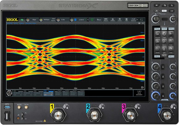
Rigol DS81304 13GHz 40GSa/s 4 Channel Digital Oscilloscope
The RIGOL DS80000 Series is a family of high-bandwidth real-time oscilloscopes engineered for advanced high-speed digital, RF, and high-frequency research applications.
The DS81304 boasts 13GHz bandwidth, a true 40 GSa/s sampling rate on every channel, and up to 4 Gpts memory to deliver uncompromised signal visibility for characterising high-speed serial links, microwave systems, and precision analogue designs. The DS81304 provide exceptional time-domain fidelity, real-time eye diagrams and jitter analysis options, and comprehensive serial protocol tools.